AMAL Remote Needle Racing Carburetter
With large top feed Float Chamber, Type 302, for Petrol and Petrol Benzol only.
(These models are not to be used with alcohol fuels)
Types:-
10 R.N.9 for 350 and 500 c.c. single cylinder engines and big twins. Made in light metal alloy.
Choke Bores 11/16", 13/32", 11/8", 15/32", 13/16".
15 R.N.9 for 250 c.c. single cylinder engines and small twins. Made in light metal alloy.
Choke Bores 7/8", 15/16", 1".
For racing machines, this R.N. design offers an advantage in the fact that the needle control operated by the throttle is placed away from the choke bore so as to leave an unrestricted passage to the inlet valve at full throttle.
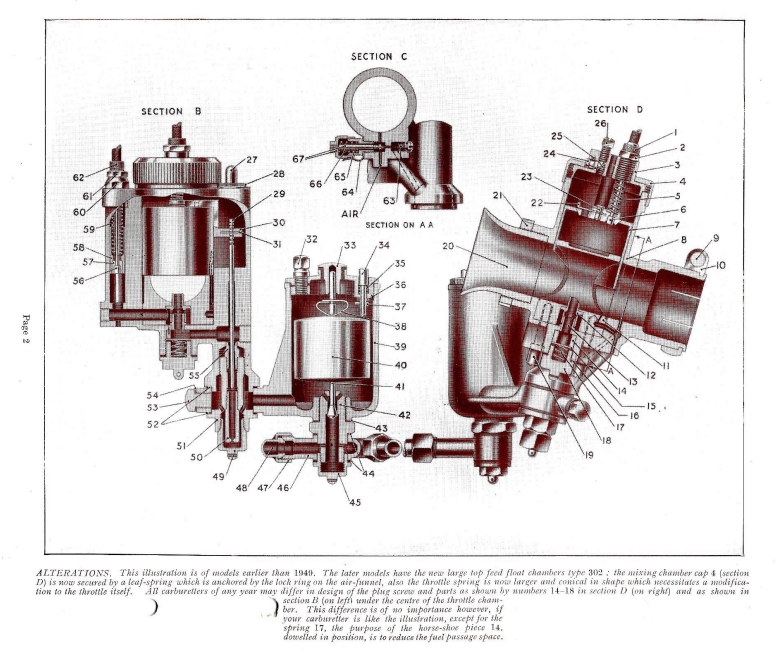
These instructions also cover the 1937/1939 models, which differ only slightly in design, except for the float chamber. The 1949/1951 models are now supplied with the Type 302 TOP FEED float chambers and have other improvements as indicated under the illustration. The principle of the working of these carburetters and the method of tuning are the same for all models of any year.
GENERAL OPERATION.
The numbers in brackets in the text refer to index numbers on the section illustration.
Float and Mixing Chamber.
The 1949 models are normally supplied with the new special top feed single float chamber which gives an exceptionally steady and ample feed for engines up to 500 c.c. per cylinder. However, bottom feed chambers have been made and are available under certain circumstances.
All float chambers for these carburetters may be attached either direct to the carburetter or may be mounted at the correct level on the frame of the motor cycle, and from there coupled to the carburetter by a flexible pipe. The petrol passes from the float chamber in both cases to the mixing chamber and flows around a bolt (51), which bolt contains the main jet (50), and the needle jet (55). The petrol passes through the main jet and up through the needle jet, the restriction there being controlled by the needle (29). The fuel then flows on through a horizontal passage under the centre of the mixing chamber, and there it mixes with the primary air, which is controlled by the valve (58) as it flows out through the primary choke (12), into the main air stream.
The throttle slide (7) of cylindrical design is operated in the normal way, but the needle (29) in this design is attached to an arm (30) at the side of the throttle. This arm lifts the needle up and down so that the mixture strength may be controlled by the needle setting at any given throttle position for any peculiarity of a particular engine.
The Air Control.
This carburetter has a hand-operated primary air control, as has been used in previous years. The carburetter is fully automatic when tuned with the air valve wide open, but the purpose of this valve when closing down is to increase the mixture strength by closing off the primary air port, and should only be used when starting from cold, or if when riding it should be apparent that the mixture was getting weak for one reason or another. The engine should not be run continuously with the primary air shut off altogether.
The Pilot Jet.
This can be seen under section C of the illustration, and is worked on the well-known basis of controlling the amount of fuel which is drawn separately from the float chamber. The pilot jet outlet is between the throttle and the engine, but it also has a secondary outlet into the choke block on the atmospheric side of the throttle, so creating a bridging device between the pilot action and the main jet coming into operation. A fixed air supply to the pilot is provided by the small hole marked AIR in the illustration (section C).
LIST OF TUNING PARTS.
- Throttle needle (No. 29, section B).
- Throttle valve cut-away (No. 7, section D).
- Pilot jet adjustment (No. 67, section C).
- Primary air control valve, operated from handlebar (No. 58, section B).
- Needle jet (No. 55, section B), this is not often changed unless the needle is placed in extreme positions.
- Main jet (No. 50, section B).
THINGS TO LOOK OVER BEFORE RACING.
- See that the petrol supply from the tank is ample, and that all passages in the float chamber and its attachment to the carburetter are clear.
- See that the tickler in the float chamber lid (34, section B) springs up.
- See that the mixing chamber top cap ring (4, section D) is screwed down (and is locked by screw (26) if there is no external security spring).
- Lock float chamber lid with screw (32, section B).
- Lock the cable adjuster nuts (2 and 61).
- Wire up the following screws:- Main jet cap (49), section B. Screws (19, section D). Petrol pipe connection to float chamber (45), section B. Screws (18, section D) and (53, section B), these plug screws should be properly tightened up on their washers.
- Finally: Make certain that the throttle (7) works freely up and down when the cables and controls are fastened into position, and when the handlebars are moved in different directions.
- If the float chamber is remotely situated, see that the flexible feed pipe between the float chamber and mixing chamber is in good order; we recommend the use of Bullite, made by the John Bull Rubber Co., Ltd.
NOTES ON DISMANTLING.
To remove throttle, or to get at needle adjustment, unscrew ring cap (4) on the top of the mixing chamber body. (In earlier models, this ring may be locked by a screw (26) near the cable adjuster, if so loosen this screw first). To detach throttle wire from throttle, withdraw flat spring (22) and remove the plug (23), then slide out the cable. When re-fitting the throttle, note the key on the side of the throttle to see that it slides in the groove in the choke block. Also note that the mixing chamber top cap (3) has a key on it to drop into a slot in the top of the mixing chamber. When replacing the mixing chamber lock ring, see that the cap (27) over the needle chamber is replaced with its holding spring (28), the edge of which is held down under the mixing chamber ring (4).
To get at the main jet, remove only cap (49, section B), but to get at the needle jet (55), remove the float chamber holding bolt (51). To remove the choke block, undo screws (19, section D). To remove float needle (41) remove float chamber lid after loosening screw (32), and remove cap (45), pinch the float bow (38), and pull out the float. The needle (41) will then drop down.
USEFUL SPARES TO HAVE WHEN TUNING UP.
Main Jets.
This jet is type No. 3326 and is the same jet as in the T.T. carburetter. It is 13/32" overall in length with a thread of 26 threads. Price, see fly-leaf, any calibration number. This jet is common to all models of R.N. carburetters.
Throttles.
These R.N. throttle valves are supplied with different cut-aways. Each type of R.N. carburetter has its own throttle, and in each type the throttles are interchangeable irrespective of choke bore. Throttles for earlier types 10 RN. Type No. 185/147. Throttles for later types 10RN9. Type No. 185/366. Throttles for earlier types 15RN. Type No. 185/148. Throttles for later types 15RN9. Type No. 185/365. For prices see fly-leaf, specify the cut-away number.
Throttle Needles.
These needles are not interchangeable with other types of carburetters, but the needles are interchangeable in types 10 and 15 R.N. carburetters. This needle is marked R.N.: when ordering a replacement needle, specify the marking on it.
Needle Jet.
This is type 185/109 for both types R.N. 10 and R.N. 15. No. 109 is standard. Price, see fly-leaf, but other sizes are available for special purposes.
Floats and Float Needles.
These Carburetters have, over a period of years, had two designs of Float Chambers so therefore, when ordering spare float or needle, please state if the float chamber lid is threaded and screwed on to the float chamber, or, alternatively, the lid is held down by two hexagon headed pins. Also, state if top or bottom feed. Up to 1948 the float chambers were as illustrated on page 2, as Spares list 417R. 1949 models and onwards, normally have the new racing float chambers, type 302, with top feed: these are identified by the lid being held down by two hexagon headed pins, see Spares list A452.
HOW TO TUNE.
First of all it must be understood that the bore of the carburetter (20) has been approved by the manufacturers of the engine as a suitable bore, and then it is for the individual rider to tune up for racing conditions and the fuel at his disposal, also it is understood that the fuel shall be straight petrol or of the petrol-benzol type. (If the carburetter is to be fed with alcohol fuels read special note on the subject). When tuning the carburetter it is assumed that the float chamber is working correctly and is not flooding, and what the rider has to do is to ensure a correct mixture at all throttle positions. There can be under these conditions only two faults in carburation - either the mixture is weak, or the mixture is rich, and it must be known at what throttle positions this richness or weakness is apparent.
The symptoms of richness are:-
- Sooty sparking plug.
- Black smoke in the exhaust and tendency to eight stroke.
- Running becomes much worse when the primary air valve is lowered, etc.
The symptoms of weakness are:
- Spitting in the carburetter.
- Over-heating.
- Engine pulls better if the primary air valve is lowered, etc.
It is to be noted that the mixture may be rich or weak at a certain throttle position but correct at another throttle position; for example:- it might be correct at half throttle, but weak at full throttle, and so for the sake of facility in tuning we mention 4 phases of throttle opening as follows, and indicate in each phase how the mixture may be corrected.
- If the throttle is almost closed as for idling, the mixture strength can be adjusted by the pilot screw (67) as seen in section C. Screw the knurled head anti-clockwise to richen the mixture, and clockwise to weaken it.
- If the throttle is ¼th to ½ open, weakness can be cured by a smaller cut-away on the atmospheric side of the throttle (7), and richness cured by a larger cut-away. The numbers of the cut-aways are marked on the top of the throttle, a No. 6 cut-away giving a weaker mixture than a No. 5 cut-away.
- If the throttle is about half open, the setting of the needle (29) as seen in section B, can be adjusted in relation to the throttle. Weakness of mixture may be cured by raising the needle in relation to the throttle position. This is done by pressing out the spring (31) and lifting the needle one or two notches. The effect of this is to withdraw the taper needle slightly in the needle-jet (55), so offering less restriction to the flow of fuel. Richness at approximately half throttle can be cured by lowering the needle. The specification of needle position is counted from the top needle groove:- For example, if the needle position 4 is recommended the clip should be in the 4th groove from the top.
- If the throttle is nearly wide open or wide open, it is very important to have the mixture rich enough at full throttle to avoid the engine overheating. The control of the mixture strength at this throttle position is by the main jet (50), which can be got at by removing cap (49). Each jet is numbered, and the bigger the number the bigger the jet. The jets are graded in tens. When selecting a suitable size main jet for speed at full throttle, the air control, as previously stated, must be wide open, but if it is found that with the air valve (58) nearly closed the engine runs better, it is an indication that the jet number should be 3 or 4 sizes larger.
SEQUENCE OF TUNING.
- 1st. Determine the main jet size with the primary air valve wide open to obtain maximum power at full throttle.
- 2nd. Adjust the pilot jet to steady regular slow running.
- 3rd. Determine the correctness of the throttle cut-away by opening the throttle very slightly to see that it "takes off" from the pilot jet on to the main jet needle position.
- 4th. Determine the needle position in relation to the throttle opening at about half throttle.
- 5th. Run over the setting again to see that the 4 phases blend together, and make final adjustments, noting that once having determined the main jet size this should not be altered.
The numbers in brackets in the text refer to index numbers on the section illustrations on page 2.
EXAMPLE OF CARBURETTER SETTINGS for petrol and petrol-benzol mixtures (approximate only).
| Engine Capacity per cylinder | Carb. Type | Choke Bore, inches | Choke Bore, m/m | Main Jet | Throttle Valve Cut-away | Needle Position | Needle Jet |
|---|---|---|---|---|---|---|---|
| 500 c.c. | 10 R.N. | 13/16" | 30·16 | 600 | 6 | 4 | ·109 |
| 350 c.c. | 10 R.N. | 13/32" | 27·78 | 500 | 6 | 4 | ·109 |
| 250 c.c. | 15 R.N. | 15/16" | 23·81 | 300 | 5 | 4 | ·109 |
ALCOHOL MIXTURES CANNOT BE USED WITH THIS TYPE OF R.N. CARBURETTER.
If alcohol mixtures have to be used, see T.T. carburetter list 374 series.