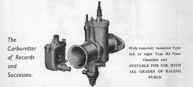
Amal GP.2 Racing Carburetter (Series 516)
GENERAL OPERATION.
DESIGN FEATURES.
The G.P.2 carburetter has been designed with a view to obtaining the maximum possible power from the engine, at the same time maintaining a progressive and consistent acceleration throughout the throttle range.
This has been achieved by embracing the metering needle (11) within the confines of the throttle valve itself (23) which, although leaving an unrestricted bore at full throttle, also leaves a very short tract for the mixture to traverse from the needle jet (1) to the choke. The G.P.2 carburetter, as distinct from the G.P. carburetter, now carries an additional feature, inasmuch as the pilot adjuster screw now controls the volume of air and the petrol is metered through a detachable pilot jet, giving much more flexible tuning over the pilot range and at the same time this arrangement has been so designed that the carburetter can be used at an increased downdraught angle and if necessary, completely downdraught.
Resulting from these points of design it will be found that in conjunction with the maximum power obtainable, a much smoother throttle control is possible at the lower r.p.m. which has the result where megaphone exhausts are used, of allowing a cleaner entry on to the megaphone than was previously possible.
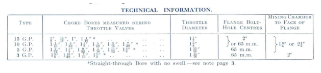
CHOKE BORE DIAMETERS.
Except in the maximum CHOKE SIZES of the four types of G.P.2 Instruments, it will be found that the effective choke diameter of the Mixing Chamber is on the engine side of the throttle slide (23), between it and the outlet of the Carburetter, and not in the centre of the choke adaptor (22) as might be expected.
Therefore, in referring to the choke size of a G.P.2 Carburetter, it is this smallest diameter in the Mixing Chamber which is of moment. Naturally, when deciding on the choke size of a Racing Carburetter, the peak r.p.m. of the engine is the main controlling factor in conjunction, of course, with the inlet port diameter on the engine in question. Therefore, when ordering one of these instruments from us it is always safer, apart from mentioning the engine, to also give us the maximum r.p.m. and the inlet port diameter, when we shall then be able to assess exactly the correct choke size of the instrument.
FITTING.
Regarding fitting the Carburetter, although we are often asked what is the correct distance between the inlet valve centre line and the centre of the Carburetter Mixing Chamber, this is not a figure which can be laid down in hard and fast manner, as it varies enormously from one engine to another, although maximum efficiency is obtained in both cases. speaking, a distance of between 7" to 9" probably represents a fair mean dimension. Broadly Flange fitting is standardised with the G.P. Carburetter to eliminate as much as possible the worrying source of air leaks which often persists with clip fitting instruments.
FLOAT CHAMBERS.
The Float Chamber recommended and normally fitted to the current G.P.2 Carburetter is a remotely mounted Type 510 and is of bottom feed design incorporating a lever type operated float. If a rigid float chamber is required our type 302 which is attached to the mixing chamber in the orthodox manner can be supplied. The float chamber can either be upright, or cranked at the angle of the induction port of the engine in question. It is, therefore, necessary when ordering a carburetter incorporating a solid mounted float chamber to state the angle of the induction port.
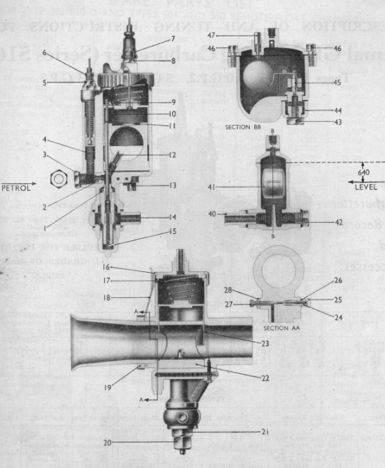
PETROL LEVEL.
The petrol level in the type 510 float chamber is 640" below the cover joint (see diagram, page 2) and is marked with a raised line on the outside of the body. In positioning the float chamber this line should be on a level with the lowest point of the circular scribe mark on the air jet plug (3).
The petrol level in the old type 302 float chambers is 1 ⁵⁄₁₆" below the cover joint and in the type 504 remote float chamber 90" indicated externally on the float chamber body. The levels on these float chambers should be positioned to line up with the lowest point of the circular scribe mark on the air jet plug (3).
LOCKING DEVICES.
A spring blade locking device (18) held in place by the air tube lock ring (19) engages with serrations on the mixing chamber cap (16), which positively prevents the unscrewing of same due to vibration. The jet plug (20), banjo bolt (43), plug screw (42), jet block holding screws (13), float chamber cover screws (46), and the float/hinge spindle head (not illustrated) are drilled to enable them to be lockwired up.
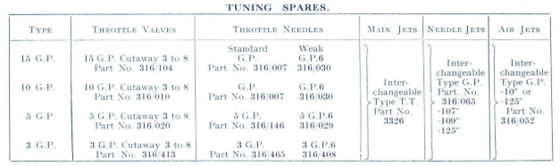
TUNING. GENERAL.
The tuning sequence of the G.P.2 Carburetter follows the well established Amal principles, inasmuch as there is a main jet (15) controlling the fuel supply at full throttle, a needle jet (1), the emission from which is controlled by the position of a taper needle (11) in same and at the lower throttle openings by the cut-away of the throttle valve (23), a detachable pilot jet (24) and a pilot air adjusting screw (27) controlling the mixture strength for idling; an air jet (2) controls the amount of air which primarily atomises the fuel as it comes out of the needle jet (1) before going into the spray tube (12) and thence to the heart of the choke. This latter air jet (2) is a form of depression control for the main jet and from normal experiences would appear to require a1" diameter air jet for choke sizes of up to 1¹⁄₁₆" and 125" diameter for choke sizes in excess of this figure. Normally speaking, this air jet would be fitted by the Factory when the carburetter was supplied and would not be considered a likely component to change, but remembering that the main jet depression can be increased by fitting a smaller air jet, it may sometimes, for special purpose tuning, be found an asset to try a larger or smaller air jet.
The NEEDLE control covers a range of the throttle opening from about one-third throttle up to seven-eighths throttle opening. The needle grooves in the G.P. needle will be found to number five instead of seven as previously on the T.T. instruments, due to the fact that the needle control of the G.P. Carburetter is rather more sensitive than on other types. Two types of needle (11) are available, what we call a standard taper needle and a much weaker taper needle. The needles in both Type 15 and Type 10 G.P.2 instruments are the same length. Consequently, the standard taper needle in these two instruments is known as the G.P. Needle the weaker taper needle in these two types of instruments is known as the G.P. 6 Needle.
With regard to the larger Types 5 G.P.2 and 3 G.P.2 instruments, their needles are longer than the ones in the two smaller types and the standard tapers are known as Type 5 G.P. and Type 3 G.P. Needles the weaker taper needle is designated the Type 5 G.P.6, and Type 3 G.P.6. The weaker needle is usually fitted except where alcohol fuel is concerned. It will then be found that the stability on the megaphone is much improved and any tendency towards weakness at the bottom of the throttle opening can, of course, be rectified by fitting a fairly low numbered throttle valve. MAIN JET. Always bear in mind, however, that whatever the type of needle used, or the position in which it is fitted, there will be no affectation of the main jet (15).
This should be arrived at by fitting the jet which gives the best possible power on the bench or, on the other hand, the highest possible R.P.M. on the road, and once this has been obtained, under no circumstances should it be altered. The main jet (15) can be very readily removed by taking off the hexagon cap (20) at the base of the Carburetter Mixing Chamber. The jet size is marked on the side of these jets, and represents the flow in c.c. per minute on our Amal Calibrating Machines at the Works.
These jets are made in 10 c.c. increments, that is, for instance-250, 260, 270, etc. up to and including 600, when, after this, 20 c.c. increments become standard up to 1,000. Over 1,000 increments are of 100 c.c.
For rough guidance, therefore, the following jet sizes should be approximately correct for the choke sizes in question :
The rest of the throttle range should then be dealt with absolutely individually in steps by means of the needle adjustment, throttle valve cut-away alteration and pilot adjustment, with a possible check on the air jet fitted.
The THROTTLE VALVE (23) which surrounds the choke adaptor (22) in the Carburetter, controls with its leading edge the velocity of air entering the throttle bore and consequently the depression on the spray tube at the lower throttle opening with a diminishing effect up to point where the cut-away disappears from the cross bore.
The trailing edge of the throttle valve, of course, controls the volume of mixture passing to the engine.
These throttle valves can be supplied with various cut-aways from No. 3 up to No. 8, each number varying in its cut-away on the air intake side by 1/16
The NEEDLE JET (1), which is of 815 manganese bronze to prevent wear, has been found for best all round usage on petrol or petrol benzole to require a diameter of 107" for choke sizes in the type T.15.G.P.2 Range, over this a needle jet of-109" diameter is necessary. For alcohol fuel, of course, larger needle jets are necessary. This is dealt with on page 6.
PILOT SYSTEM.
This gives a supply of metered fuel through a detachable pilot jet (24), which mixes with air regulated by the pilot air adjusting screw (27) and passes into the mixing chamber through a small hole on the engine side of the throttle slide.
COMPENSATION on this G.P.2 Carburetter is obtained through the medium of the primary air which passes through a slot (4) in the Mixing Chamber and then, via the air jet (2) previously mentioned, atomises the liquid fuel passing from the needle jet (1).
As the engine supply increases or decreases at a given throttle opening with a varying load, compensation will take place.
KEY TO SECTIONED ILLUSTRATION.
MIXING CHAMBER.
- 1. Needle Jet.
- 2. Air Jet.
- 3. Air Jet Plug.
- 4. Primary Air Slot.
- 5. Air Valve Cable Adjuster Locknut.
- 6. Air Valve Cable Adjuster.
- 7. Throttle Cable Adjuster.
- 8. Throttle Cable Adjuster Locknut.
- 9. Needle Clip.
- 10. Needle Clip Retaining Screw.
- 11. Metering Needle.
- 12. Spray Tube.
- 13. Choke Adaptor Retaining Screws.
- 14. Petrol Inlet Banjo.
- 15. Main Jet.
- 16. Mixing Chamber Cap.
- 17. Throttle Valve Return Spring.
- 18. Mixing Chamber Cap Lock-Spring.
- 19. Air Tube Lock Ring.
- 20. Jet Plug.
- 21. Jet Holder.
- 22. Choke Adaptor.
- 23. Throttle Valve.
- 24. Pilot Jet.
- 25. Pilot Jet Cover Nut.
- 26. Pilot Jet Cover Nut Washer.
- 27. Pilot Air Adjusting Screw.
- 28. Pilot Air Adjuster Locknut
FLOAT CHAMBER.
- 40. Petrol Outlet Connection.
- 41. Float and Hinge.
- 42. Plug Screw.
- 43. Petrol Inlet Banjo Bolt.
- 44. Petrol Inlet Banjo.
- 45. Float Needle.
- 46. Float Chamber Cover Screws.
- 47. Tickler.
TUNING SEQUENCE.
To get carburation for any stated fuel when the choke bore is correct for the peak revs. of the engine and the correct needle jet for the fuel to be used, the procedure is simple. Start off with an assumed setting, and then tune as follows. There are four phases:
- (1)-Main jet for power at full throttle;
- (2)-Pilot Air Adjuster for idling;
- (3)-Throttle cut-away for "take off" from the pilot jet;
- (4)-Needle position for snappy mixture at quarter to three-quarter throttle; then final idling adjustment of the pilot jet.
Always tune in this order, then any alteration will not upset a correct phase.
SEQUENCE OF TUNING.
- (1)-Main jet size.
- (2)-Pilot adjustment.
- (3)-Throttle valve cut-away.
- (4)-Needle position.
-
MAIN JET SIZE. This should be determined first the smallest jet which gives the greatest maximum speed should be selected, keeping in mind the safety factor for cooling. (The air lever should be fully open during these tests).
-
PILOT ADJUSTMENT. Before attempting to set the pilot air adjuster the engine should be at its normal running temperature, otherwise a faulty adjustment is possible, which will upset the correct selection of the throttle valve. The pilot air adjuster is rotated clockwise to richen the mixture, and anti-clockwise to weaken it. Adjust this very gradually until a satisfactory tick-over is obtained, then reset locknut but take care that the achievement of too slow a tick-over- that is, slower than is actually necessary-does not lead to a "spot" which may cause stalling when the throttle is very slightly open.
-
THROTTLE CUT-AWAY. Having set the pilot air adjuster, open up the throttle progressively and note positions where, if at all, the exhaust note becomes irregular. If this is noticed, leave the throttle open at this position and close the air lever slightly; this will indicate whether the spot is rich or weak. If it is a rich spot, fit a throttle valve with more cut-away on the air intake side (or vice versa if weak).
-
JET NEEDLE POSITION. Tuning sequence 2 and 3 will affect carburation up to somewhere over one-quarter throttle, after which the jet needle, which is suspended from the throttle valve, comes into action and when the throttle is opened further and tests are again made for rich or weak spots, as previously outlined, the needle can be raised to richen or lowered to weaken the mixture, whichever may be found necessary. With these adjustments correctly made, and the main jet size settled, a perfectly progressive mixture will be obtainable from tick-over to full throttle. The jet needles are interchangeable in carburetters type 15 G.P.2 or 10 G.P.2, but longer needles are required for the Type 5 G.P.2 and Type 3 G.P.2.
ALCOHOL FUELS.
Concerning Alcohol fuels, the G.P.2 range of Carburetters function perfectly satisfactorily on any alcohol blend up to and including straight methanol. It will be necessary to fit a125" diameter needle jet (1) for any alcohol content over 50%. With this larger needle jet a standard taper needle (11) should be used, which means for the Type 15 G.P.2 a needle marked G.P. is required, for the Type 10 G.P.2 a needle marked G.P. is required (both these types using the same needle); for the Type 5 G.P.2 a needle marked 5 G.P. is needed, and for a type 3 G.P.2 a needle marked 3 G.P. is needed. An approxi- mately correct needle position will be No. 4, that is the fourth groove from the top of the needle. Regarding main jet sizes, these have to be increased in the following proportions, taking the basic size as that used for 80 octane fuel or petrol benzol.
| Fuel | Increase the basic jet size by |
|---|---|
| Straight Methanol | 150%. |
| J.A.P. Racing Fuel | 150%. |
| Esso No. 1 Fuel | 150%. |
| Esso No. 2 Fuel | 120%. |
| Esso No. 3 Fuel | 130%. |
| Shell A.M.M. Fuel | 150%. |
| Shell A.M.1 Fuel | 140%. |
| Shell A.M.8 Fuel | 120% . |
| Shell A.M.9 Fuel | 100%. |
| Shell A.M.12 Fuel | 50%. |
NOTE, When calculating the jet size on the basis of the jet size used for petrol-benzol mixtures the per cent. increase must be added to the original jet size and the total is the new size of jet to be used for the particular fuel. EXAMPLE: If a Jet No. 300 was used for petrol-benzol and it was decided to change over to METHANOL, which requires an increase of 150% adding to the original jet size 300. Calculate this way:
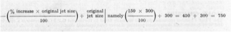
The answer is, use main jet 750 and the appropriate needle-jet for alcohol fuels as given in a paragraph above. When using alcohol mixtures, the alcoholic content of which is not exactly known, "trial and error" will be necessary in finding the correct jet size, in which case it should be remembered that although quite an excessively over-rich mixture can be used on alcohol, the slightest weakness will result in trouble. Therefore, always err on the rich side for the start of the "trial and error" tests. On the other hand, if the exact composition of the fuel should be known and you get in touch with our Technical Department, they will be able to give you a fairly close approximation of the jet size required for the alcohol mixture in question.
Normally, when changing over from petrol to alcohol on the G.P. range of Instruments, no alteration will be necessary to the air jets fitted.
Download Original Document Here