Type 120 Fuel Pump Instructions
Note: The filter "M" may be a unit construction as illustrated, or alternatively, the gauze "M" may be detachable and held in position by a loose ring screwed onto the adaptor, which is the non-return valve seating. This ring having projections which contact and indentation in the filter bowl should it or the vavle seating attempt to screw loose.
Brief Operating Instructions
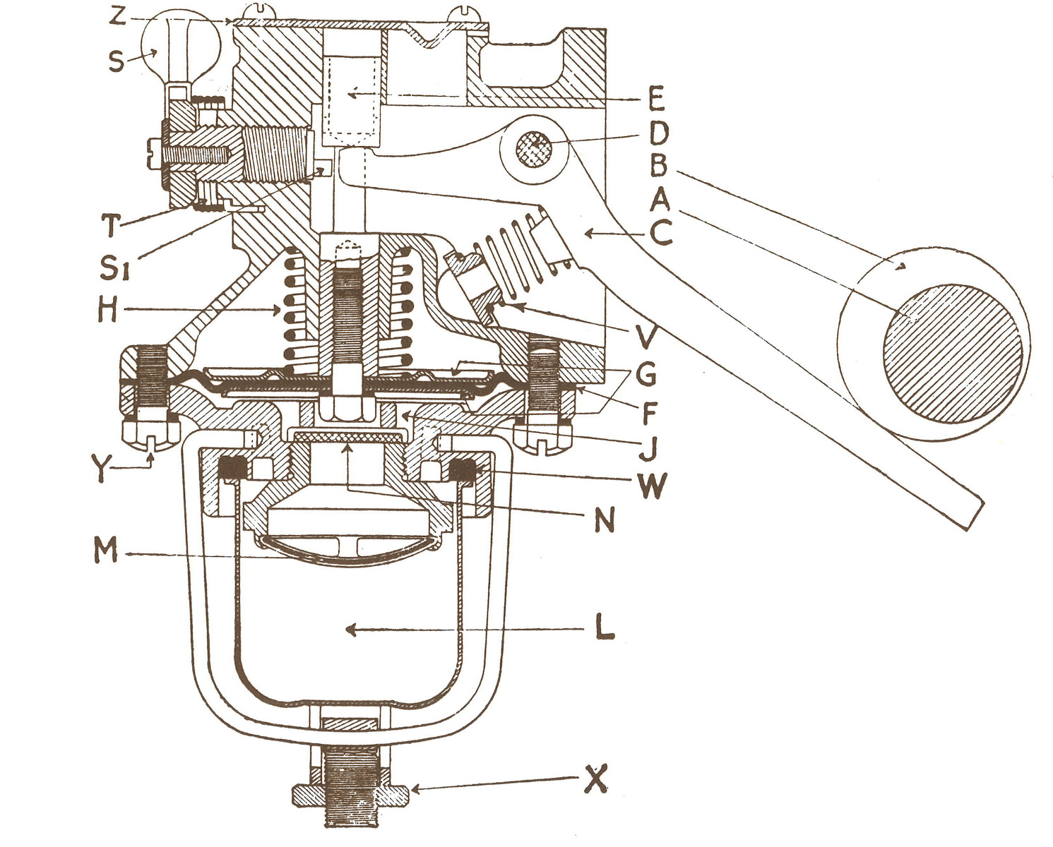
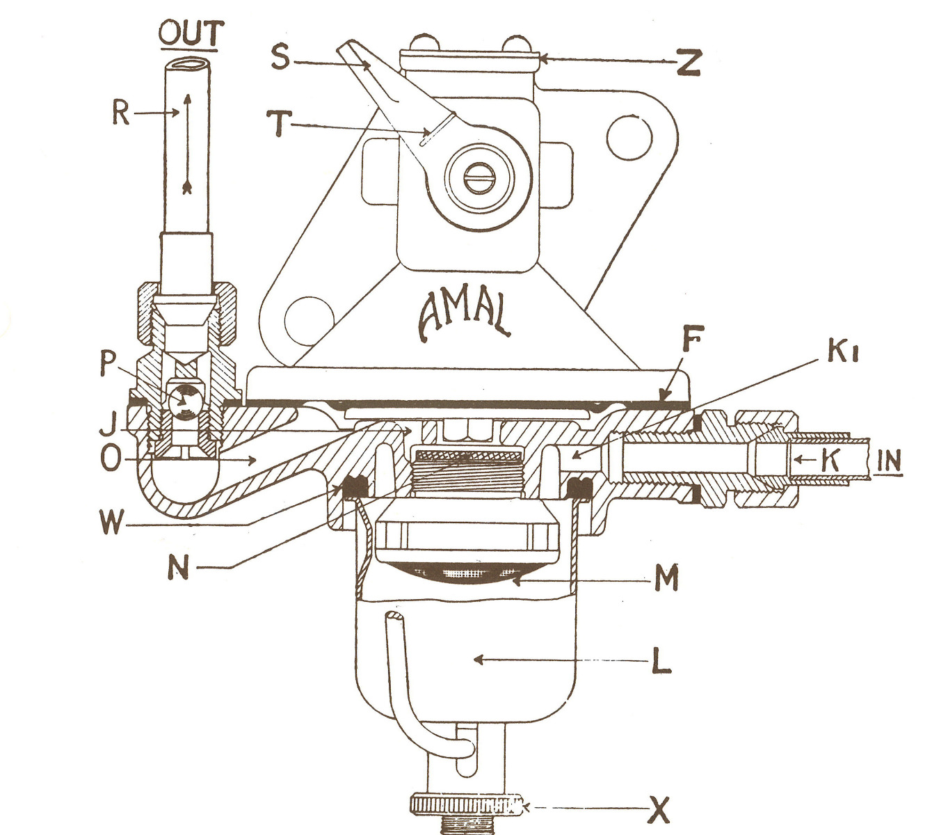
The shaft A which is usually the camshaft on the engine, carries an eccentric B; this operates a rocker arm C pivoted at the point D. When the shaft A revolves, the rocker arm C lifts the spindle E to which is fixed the diaphragm F, which is interposed between two metal discs G, so inducing petrol to flow from the tank up the pipe K through passage K1 into the filter sump L through filter M and the suction disc valve N into the pump chamber J.
The shaft A continues to revolve, and the diaphragm F commences its downward stroke solely under the influence of spring H. The suction valve N closes and the fuel is forced along the passage O past the delivery valve P and up the pipe R to the carburetter.
When the carburetter float chamber is filled, the float will shut off the inlet needle valve, thus creating a pressure in the pump chamber J. This pressure will react against diaphragm F (against the spring pressure H) causing it to remain in the 'raised' position.
The lever C under these conditions can no longer give the spindle E any movement, due to the fact that it is raised beyond the point where the lever engages with the spindle. The lever then simply moves backwards and forwards idly and whe nthis occurs the pump can no longer deliver fuel unitl such a time as the needle valve opens in the carburetter.
The pressure in the pump chamber J then falls and allows the spindle E to drop and once more come in contact with the lever. The spring H is set to a pre-determined pressure and this cannot be exceeded under any circumstances of the pump's operation. The spring V is for the purpose of maintaining the rocker arm C in contact with the eccentric B to prevent noise and it has no action on the fuel pump itself.
The inspection cover Z can be removed to check the setting of the pump which is: the top of the spindle should be 1/8" to 1" below the top face of the pump in its highest position. The filter sump L is removed for cleaning purposes by unscrewing the knurled nut X, the filter M can then be unscrewed cleaned and replaced. The sump is then fitted and screwed up tightly to make an air-tight joint by means of washer W.
The priming lever S is then operated by hand. This brings the part of the priming lever S1 in contact with the spindle E, so working the diaphragm: about a dozen slow strokes is all that should be necssary for petrol to reach the float chamber in the carbruetter. When this occurs and the float chamber is full, the resistance to movement of the priming lever S will gradually diminish until it is felt that it ceases to act. This means that the float chamber is full and the diaphragm is raised under pressure so produced in the pump chamber J and no further actuation of the priming lever is necessary. The priming lever is held back when not in use by the return spring T.
Service Hints and Tips
Do not entirely dismantle the pump unless it is necessary to examine the diaphragm and the spindle. Normal cleaning can be done under the section A and B below.
Section A
For normal cleaning it is only necessary to remove the the filter cup by loosening the stirrup nut and swinging the stirrup to one side. The cup will then fall away exposing the filter gauze. The gauze can be removed for cleaning and if the adaptor onto which it fits also screws out, care must be taken not to damage or lose the suction valve N.
When replacing these parts see that the washer W is in good order, as any bad fit here would cause leakage of fuel or even an air leak, which could upset the function of the pump. The nut X when centred in the cup should be screwed up firmly.
Section B
If it is desired to clean out all the fuel passages, this can be done without disturbing the diaphragm and without taking the two halves of the pump apart, as all passages are underneath the diaphragm.
1. Disconnect the fuel pump connections K and R from the pump and remove the pump in its entirety from the engine by undoing the flange bolts.
2. Remove the filter bowl as per section A above and also the suction valve N and its seating.
3. To inspect the delivery valve P in the outlet pipe, unscrew the hexagon cage from the lower half of the pump. The ball valve seating with the screwdriver slot may be unscrewed from the underside and the ball valve will fall away.
4. All parts may now be flushed out with petrol and reassembled. it is to be noted that neither in the suction valve nor theball delivery valve are there any springs. Nothing needs to be looked at with these types of valves apart from an accumulation of dirt.
The pump can only fail to function for two reasons:
Firstly actual mechanical breakage which will be obvious but very unlikley to occur. Secondly it could fail due to internal air leaks, which should be examined in the following order:
1. The connection between the filter sump L and the pump. See that the knurled nut X is screwed up tight and that the joint washer W is in good condition.
2. Check for air leaks in the inlet tubing between the tank and the fuel pump, making certain that all the joints and unions are tight and there are no cracks in the pipe itself. The same remarks apply to the tubing between the fuel pump and the carburetter.
3. Examine the six bolts which hold the halves of the pump together. Ensure these are tight.
Section C - Instructions for complete dismantling and reassembling of the fuel pump
1. Disconnect the fuel pump as indicated in section B.
2. To remove the diaphragm spindle E it is necessary to withdraw the priming cam S1. To do this remove the small screw and washer from the priming lever S, unhook the spring T from where it grips the lever and the prise off the lever itself and detach the spring. Lift the spindle E by depressing the rocking lever C and unscrew the priming cam three or four turns.
3. Removal of the operating lever. If the pump is operated by a long lever protruding from the pump (as illustrated above) there is no need to remove the cover plate. Remove the split cotter pin holding the rocker pivot D in position, tap out the pivot pin and remove the lever as well as the spring V. If the pump is operated by a plunger instead of the lever, remove the top plate Z and extract the spring.
4. To take apart the two halves of the pump unscrew the six securing screws Y from the and gently separate the two halves which clamp the diaphragm together.
5. The diaphragm F together with the spindle E and spring H can then be withdrawn from the pump. If it is desired to inspect the diaphragm leaves, these can be removed from the spindle by unscrewing the hexagon headed pin. On earlier models this cannot be removed until the rivet through the spindle positioned about 1/2" from the diaphragm has been knocked out. Take care not to bend or bruise the spindle E.
After examination of the diaphragms or fitting of new ones they can be reassembled. The diaphragms are shaped and must be fitted correctly with the larger recess fitted uppermost (see illustration) to encircle the larger disc G. Ensure when fitting the smaller disc underneath it fits properly into the recess on the underside of the diaphragm. fit the washer under the hexagon headed pin and smear the thread with 'loctite' prior to refitting.
Care must be taken before tightening up the hexagon headed pin that the bolt holes in the diaphragm leaves are aligned. To ensure correct alignment a couple of the screws Y may be put through the holes in the edge of the diaphragm.
6. When all parts are cleaned and ready for reassembly, see that the spindle is clean, slip over the spring H and insert into position. Places the screws Y through the bottom half of the pump, through the holes in the diaphragm and then start screwing into the top half of the pump. It is necessary to reassemble the rocking lever C and itsreturn sping V onto the pin D when placed through its holes in the body and replace the split pin through the external boss of the bearing and through the pin itself.
Having done this, proceed to re-fix the priming lever S. Now lift the spindle E by depressing the rocker arm. Screw in the priming lever cam S1 as far as it will go, then come back one or two turns. Finally adjust in such a position that the spindle moves freely up or down with the cam pin sufficiently far forward to engage with the spindle and also with the flat end of the cam spindle in a vertical position so that the lever with the return spring T can be re-assembled, and that the engagement stop drops over the stop on the body. The spiked end of this spring fits into a small hole in the casing and the hooked end is sprung over the lever.
Continue to screw the pins Y finger tight and then, by means of the priming lever S, draw up the spindle with the diaphragm to the highest positionpossible by moving the lever over as far as possible in a clockwise direction, then tighten the screws securely. This ensures the diaphragm is correctly fitted in position. It should be verified that the rocker arm C will lift the diaphragm and fall easily under the action of spring H when the rocker arm is released. Also check the priming lever S will also lift the diaphragm.
7. All parts should now be reassembled as noted in section B.
8. If the inspection plate Z has been removed, it is possible to see the mmovement of the spindle under the influenece of the priming lever or the rocking lever C. Unless the moevment is free the pump must be dismantled again and reassembled. All parts should be tight to avoid either fuel or air leaks and the pump may be re-fitted to the engine.
9. If the pump is a plunger type (not illustrated), replace the rocking lever and its pivot pin D and then replace the spring for the lever in the hole under the plate Z which is fastened down by small screws.
10. The diaphragm spindle is lubricated from the engine.