Instructions for Amal Carburetter Type 32
HOW THE CARBURETTER WORKS
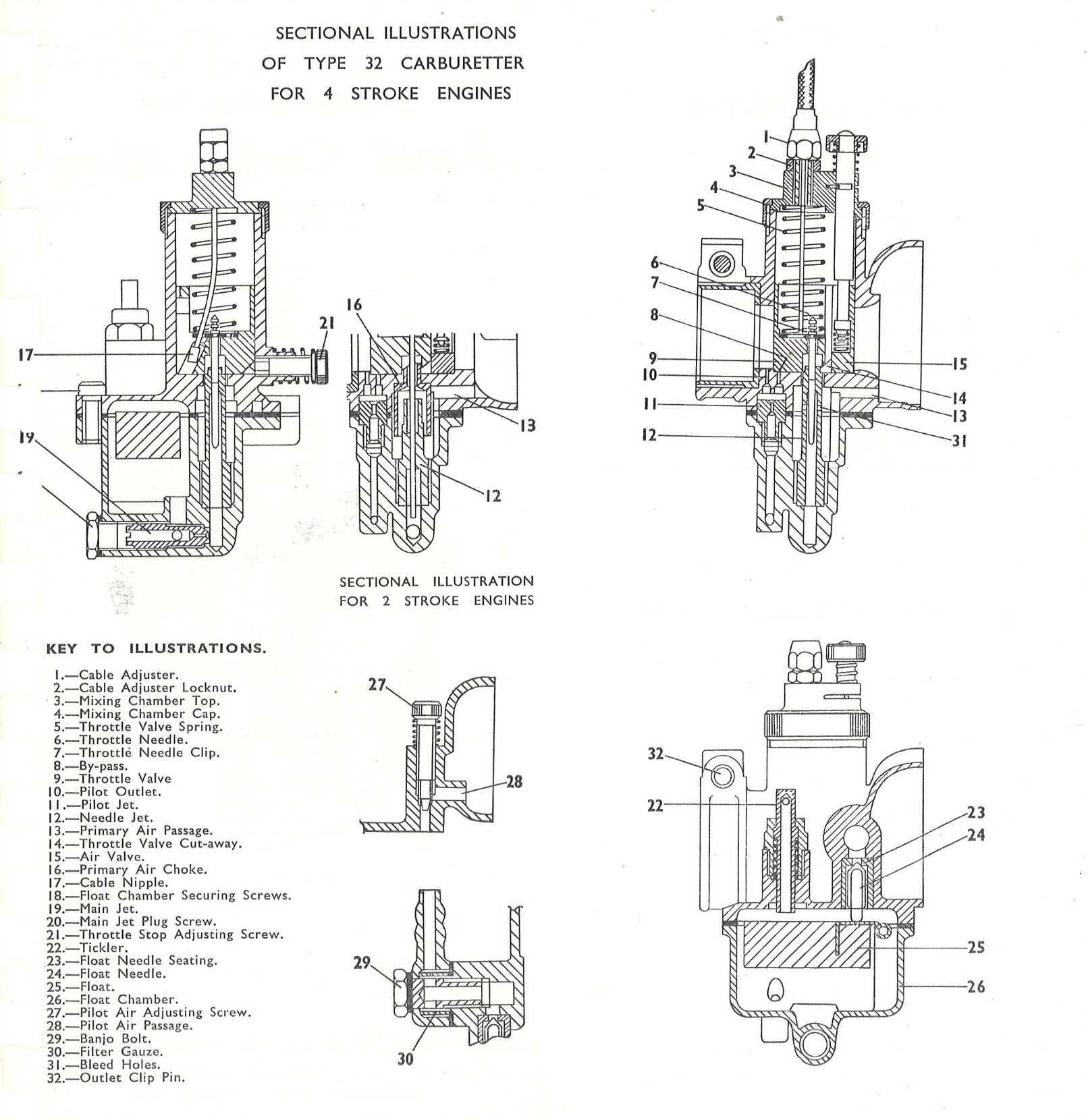
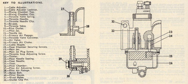
The carburetter atomises the correct amount of petrol with air which is drawn into the engine. A float chamber maintains a constant level of fuel at the jets and cuts off the fuel supply when the engine stops. For cold starting, both a tickler (22) for flooding and an air valve (15) are fitted. A throttle valve (9), operated by a cable from the handlebar controls the volume of mixture and, therefore, the engine power. At all openings of the throttle the mixture is automatically correct.
At small throttle openings, as for starting, idling and slow-running, a petrol/air mixture is drawn from the pilot jet system, fuel being fed via the passage in the float chamber to the pilot jet (11), where it mixes with air entering the pilot air passage (28), the resultant mixture then passing out of the pilot outlet (10) and by-pass (8), where it mixes with air passing through the main air choke.
For four-stroke engines further opening of the throttle enables fuel passing through the main jet (19) and needle jet (12) to be mixed with air from the primary air passage (13) and bleed holes (31) in the needle jet, then out into the main air choke where it is further mixed with the main incoming air stream.
In the case of the two stroke engines air from the primary air passage mixes with fuel from the needle jet in the primary choke prior to dis- charging into the main air stream. Up to quarter throttle opening the cut-away (14) on the throttle valve influences the air passing through the main choke. From quarter to three-quarter throttle opening the fuel supply for the mixture from the primary choke (16) or needle jet (12) is governed by the taper of the throttle needle working in the needle jet and from three-quarter to full throttle by the size of the main jet.
STARTING INSTRUCTIONS STARTING WHEN ENGINE IS COLD.
Turn on fuel supply, set ignition, if manually operated, for best slow running depress tickler sharply three or four times to flood float chamber, close air valve, open throttle slightly and start engine. When engine starts open air valve and close the throttle; if engine begins to falter, partially close the air valve until engine is warm, then set in fully open position.
STARTING WHEN ENGINE IS WARM.
Open throttle slightly and start engine. It should not normally be necessary to flood the float chamber or close the air valve when starting a warm engine.
GENERAL.
Experience will show when it is necessary to flood the carburetter or use the air valve and also the best setting of the throttle valve. If the carburetter has been over-flooded or strangled, which would result in a wet engine and over-rich starting mixture-fully open the throttle valve and air valve, give the engine several turns to clear the richness, then start again with the air valve fully open and the throttle valve slightly open. If the engine refuses to start after the instructions given have been carried out and the carburetter is suspect, read and carry out the instructions given in the section headed "Maintenance."
MAINTENANCE OF CARBURETTER CABLE CONTROLS.
CABLE CONTROLS
Ensure there is a minimum of backlash in the cable when the throttle valve is in the closed position. Adjustment is provided by adiuster (1) and Locknut(2). Check that the throttle valve will fully open and that handlebar movement does not operate the throttle.
FITTING CARBURETTER
Erratic slow running is often caused by air leaks. Check that there is none at the point of attachment of the carburetter to the engine. The carburetter should be a good push fit on the induction pipe and the outlet clip pin (32) tightened if the carburetter is removed, when refitting put a spot of oil on the induction pipe and push carburetter on with a screwing motion; make sure carburetter is fully home before tightening outlet clip pin.
PETROL FEED
Ensure ample petrol supply is reaching carburetter; check by removing banjo bolt (29) and examining filter gauze (30) for foreign matter or damage. Before replacing turn on petrol tap momentarily and see that fuel gushes out. Petrol pipe with vertical loops causes air locks and should be avoided. Flooding may be due to a worn needle or leaky float but with new machines is mainly caused by impurities in the tank, so clean out float chamber periodically until the trouble ceases; if this trouble persists the tank may be drained and swilled out, etc.
FLOAT CHAMBER
Continual flooding of the float chamber is caused by the float needle not shutting off correctly due to foreign matter being on either the float needle (24) or its seating (23). Access to the float chamber for cleaning is by removing the three float chamber screws (18) and withdrawing the float chamber, together with its float needle and joint washer, down off the mixing chamber. Take care not to damage the joint faces. Removal of the float is by inverting the float bowl. Flush the float chamber and needle seating and wipe the float needle clean; do not attempt to clean by scraping. On old machines failure of the float needle to shut off may be due to wear on the needle or its seating, or a leaky float. Replacements should be fitted.
When replacing the float chamber assembly care should be taken to ensure that the throttle needle (6) locates in the needle jet and the float needle (24) is replaced point uppermost.
PILOT JET (11) AND NEEDLE JET (12)
These are removable after dismantling the float chamber following the instructions given under float chamber. Wash in clean petrol and blow through the passages; do not prod or reamer jets. On old machines, if wear is evident on the needle jet a replacement should be fitted.
MAIN JET
To clean, remove the main jet chamber plug (20) then with a screwdriver remove main jet (19). Wash in clean petrol and blow through orifice.
THROTTLE NEEDLE (6) AND THROTTLE VALVE (9)
Check that the throttle valve with its throttle needle moves freely up and down when the control is operated. On old machines check that no undue wear has taken place between the throttle valve and the bore in which it operates, and on the portion of the throttle needle that operates in the needle jet. If wear has taken place replacement parts should be fitted. The throttle valve complete with throttle needle and air valve assembly and attached to the cable can be withdrawn from the carburetter after the knurled mixing chamber cap (4) has been unscrewed. To separate the throttle valve and throttle needle from the cable, release the cable at the control end and push the inner cable forward in the throttle valve until the nipple (17) in the throttle valve clears its hole, then withdraw the cable through the slot in the throttle valve, the nipple passing through the hole at the extreme end of the slot.
On re-assembling, pass the nipple through the throttle needle clip and the hole inside the throttle valve then draw the cable forward until it will pass over the throttle valve and sink into its hole. When replacing this throttle assembly see that the slot in the throttle valve engages on the key in the carburetter body, that the throttle needle clip is correctly located and the throttle needle is entering the needle jet, before attempting to push the assembly home.
CARBURETTER BODY
Check that there are no stoppages in the carburetter body. This seldom occurs, but if so, the most likely places will be the pilot outlet (10) or by-pass (8). These can be cleared by unscrewing the pilot air adjusting screw (27) until it is held in by two or three threads, removing air filter and blowing through the pilot air passage with a tyre pump.
An alternative method would be to detach the float chamber and blow through the pilot outlet and by-pass with a tyre pump. The carburetter must be re-adjusted for slow running after disturbing the setting of the pilot air adjusting screw.
PARTS WITH CARBURETTER WHICH THE IS ADJUSTED OR TUNED
Main Jet (19).
Main jets may be had with varying flows, the number on each jet signifies a certain flow, the higher the number the larger the flow, the numbers going up in increments of 5 up to number 100, and after by increments of 10.
Pilot Air Adjusting Screw (27).
By screwing this in or out the amount of air entering the pilot system is varied.
Throttle Stop Adjusting Screw (21).
This screw acts as a stop for the throttle valve, by its adjustment the amount the throttle valve is kept open for idling or slow running when the control is in its shut-off position can be varied.
Throttle Valve Cut-away (14).
The slope on the throttle valve is called the cut-away and its number is stamped on the bottom of the throttle valve. Throttle valves can be had with different cut-aways-the larger the cut-away the higher is the number and the weaker the throttle valve.
Throttle Needle (6) and Clip (7).
The throttle needle is positioned in the throttle valve by clip (7). The Top of the throttle needle is grooved and by springing the clip off, and springing it on again in another groove, the position of the throttle needle in the throttle valve and relative to the needle jet is altered, either being raised or lowered.
ADJUSTMENT AND TUNING OF CARBURETTER
A certain amount of adjustment is provided for on the carburetter to ensure that a correct mixture is obtained. The correct mixture is one that is neither too rich nor too weak. See that there are no faults as outlined in "Maintenance" as these would affect the correct functioning and adjust- ment of the carburetter. Check that the ignition, timing, etc., is functioning correctly.
Carburetters as supplied by the makers for fitting to specific machines should under normal conditions only require adjustment of the throttle stop adjusting screw (21), pilot air adjusting screw (27) and the position of the throttle needle (6) to ensure best starting, idling, slow and general running with maximum fuel economy. See "Adjustment of Carburetter."
For special conditions or adaptations, or where it is suspected that the carburetter may have had an unsuitable throttle valve or main jet sub- stituted, as these parts vary according to engine requirements, it will be necessary to completely re-tune the carburetter. See "Complete Tuning of Carburetter.'
ADJUSTMENT OF CARBURETTER
First, if possible, run engine until warm, then shut off. Screw in the pilot air adjusting screw (27) as far as it will go without strain, then unscrew it in an anti-clockwise direction approximately I turns. Unscrew the throttle stop adjusting screw (21) so that the throttle valve can fully close then with the throttle slightly open start the engine and throttle down to a fast idling speed. Now, first set the throttle stop adjusting screw to hold this position, and then unscrew it to allow the throttle valve to be further closed and the engine to slow down until it begins to falter, then screw the pilot air adjusting screw in or out until the engine runs regularly and faster. Then further unscrew the throttle stop adjusting screw until the closing of the throttle valve again makes the engine run slower and just begin to then again adjust the pilot air adjusting screw to get best slow running. If, after this second adjustment, the engine is still running too fast, carry out the same procedure a third time. After each adjustment of the throttle stop adjusting screw and pilot air adjusting screw, test that the engine does not falter or cut out when the throttle is opened fairly quickly; if the engine does falter or cut out, the adjustment has been set for too slow running, resulting in an over-weak pilot mixture.
Now try the throttle needle (6) in as low a position as possible-viz., with the clip (7) in a groove as near the top of the throttle needle as possible; if when engine is under load or pulling acceleration is poor, or there is spitting-back in the carburetter, raise the needle by two grooves. If very much better try lowering the needle by one groove and leave where it is best. In general, if the engine runs heavily and lumpy the mixture is too rich and will be the cause of excessive petrol consumption, but if there is spitting-back in the carburetter, poor acceleration or over-heating, the mixture is too weak.
After the best position of the throttle needle has been found again check over the slow running.
COMPLETE TUNING OF CARBURETTER
Check as follows, and in the order given.
1st-Size of Main Jet.
With the engine pulling or under load, open up to full throttle, if at full throttle the engine runs heavily the main jet (19) is too large, resulting in a rich mixture. If at full throttle, by slightly closing the throttle, the engine seems to have better power, the main jet is too small, resulting in a weak mixture.
Examination of the sparking plug will also help to determine whether the mixture is correct. If the plug body at its end has a cooled appearance, the mixture is correct; if sooty, the mixture is too rich; if however, there are signs of intense heating, the mixture is too weak.
2nd-Idling and Slow Running.
Adjust the throttle stop adjusting screw (21) and pilot air adjusting djusting screw (27) as instructed in n "Adjustment of Carburetter."
3rd-Amount of Throttle Valve Cut-away.
If there is objectionable spitting from the carburetter when the throttle is opened up from the idling or slow running position, which signifies weakness, first try slightly richening the pilot mixture by screwirg in the pilot air adjusting screw (27) sufficiently, but if this is not effective, screw it back again and fit a throttle valve with a smaller cut-away (14). If the engine jerks under load at this throttle position and there is no spitting, either the throttle needle is in a much too high position, or a throttle valve with a larger cut-away (14) is required to cure richness. ay (14) is required to cure richness.
4th Position of Throttle Needle
Adjust position of throttle needle (6) as instructed in "Adjustment of Carburetter."
5th Idling and Slow Running.
Go over the idling and slow running adjustment for final touches.