Amal Otan Non-Return Valve
The Amal Otan non-return valve has two main advantages. Firstly at an absolute minimum return pressure the non-return system activates, cutting off any return flow. Secondly, should the return flow pressure increase, a secondary valve system closes and is held in position by means of diaphragms. Should the valve be subjected to excessive flow a domed hauze prevents the diaphragms from sticking to the metal cover.
As there are no levers or links in the valve the possibility of mechanical failure is avoided and the valve then only requires mounting in a visually horizontal position to ensure satisfactory operation.
To facilitate inspection all parts of the valve are easily accessible once the top cover has been removed. This makes in unecessary to remove the valve from the line of inspection. The design of the valve is such that drainage is catered for and condensation can be drained by simply removing the plug.
Positioning
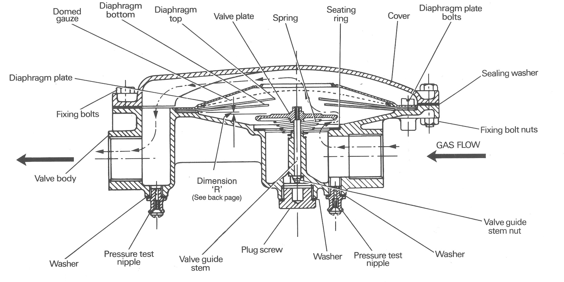
The section drawing shows the non-return valve in an operating position. The valve body is fitted with horizontal pipe connections so that when fitted in line the valve lies in the horizontal plane. It is important that this position is maintained when the valve is installed.
Operation
Gas enters and flows through the valve as indicated by arrows in the diagram. As gas passes through the valve it lifts the diaphragms off their seats on brass spring loaded valve head, allowing gas to flow through the valve with minimum pressure drop.
The slightest return pressure causes the diaphragms to fall back on their seats preventing any return flow. Should the return pressure increase, the metal valve head closes effectively producing a second seal. Under these conditions the valve can withstand very high back pressure. When the valve is in the fully closed position both diaphragms lie on the casting so there is no possibility of them being ruptured.
Installation Instructions
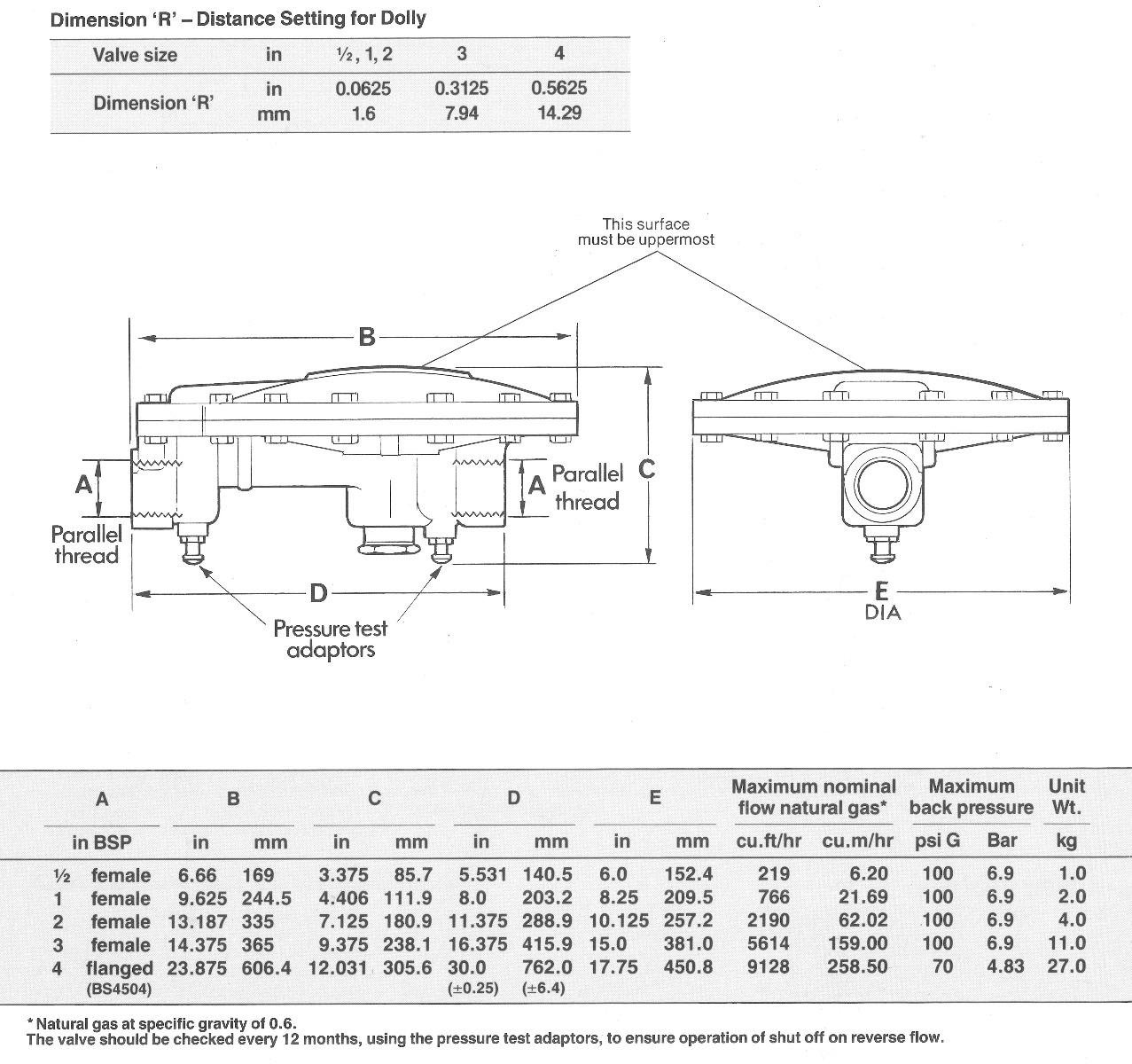
The valve must be installed so that the plane of the central flanges is horizontal, with the valve cover uppermost. The valve must be maintained in the horizontal position to within -/+ 3 degrees. In this position the bottom central plug will be facing vertically downwards so facilitating drainage of condensate.
It is suggested that shut off valves be installed both upstream and downstream of the non-return valve, as close to it as possible to facilitate isolation. Note: before connecting, the inlet and outlet pipes should be blown free of dirt or debris.
Commissioning and testing instructions
The valve must be isolated from the rest of the pipe system in which it is installed. Using a screwdriver, remove the plugs from the centres of the two test adaptors located either side of the bottom drain plug. Connect a source of low pressure air (0 to 10 mbar) to the downstream test adaptor. The connecting line should contain a T-piece and cock so that a manometer can be fitted.
The upstream test adaptor should be connected to a bubble detector capable of detecting flow at a pressure of 0.25 mbar. If no proprietary bubble detector is available the tube can be clamped so that the end just breaks the surface of a beaker of water, giving a water seal of about 0.25 mbar.
Air should then be fed into the downstream side of the valve at a rate to give a pressure of 2.5 mbar. Initally the bubble detector will show many bubbles since the diaphragm movement, as the pressure is applied, causes displacement of air in the upstream side of the valve. Once displacement is complete the bubbles should stop, but continuous bubbling means that the diaphragms are not sealing and the valves require examination.
If the valve is satisfactory at 2.5 mbar the pressure should be increased to 10 mbar. Displacement of air will again occur while pressure inceases. At 10 mbar on the outlet side of the valve the diaphragms and secondary seal should be fully closed and all bubbling should stop. If this requirement is not met the valve must be examined to ensure seatings are clean.
After commissioning, the above test should be apllied at intervals of 12 months to check the continuing performance of the valve.
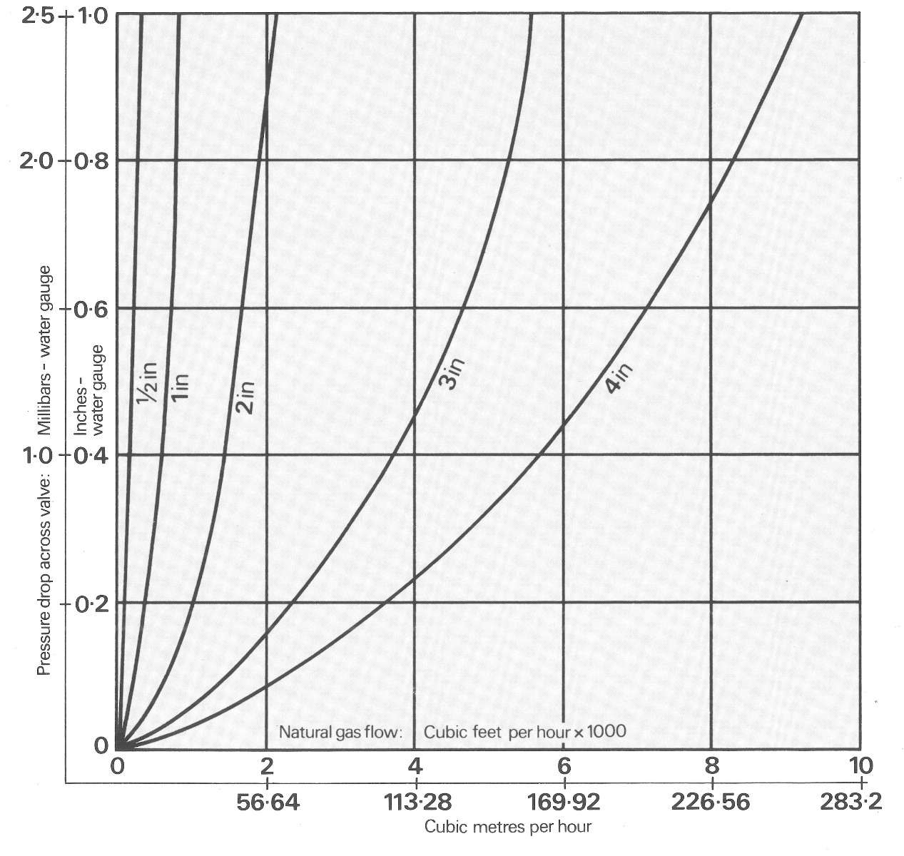
Valve flow characteristics
Servicing
The valve should be checked and serviced every 12 months to ensure correct operation. To service remove the top cover by unscrewing the fixing bolts. The diaphragm plate is then exposed. Withdraw cheese-headed screws followed by diaphragm plate and gauze, thus exposing the diaphragms. Remove diaphragms carefully ensuring they are not distorted.
Check valve plate works freely up and down against the spring and the valve seating ring is in good condition. If dirt is evident, remove the body plug screw and washer, unscrew the self locking valve stem nut so that the valve plate and spring can be withdrawn. Clean out dirt carefully, removing any particles on valve seating ring. The seating ring is secured to the body with Seccotine.
Valve seating ring and diaphragms should be re-oiled before being replaced (use medium viscosity mineral oil, Shell Vitrea No. 100). Heat to not more than 60ºC, pour into tray and soak diaphragms completely; blot off excess oil. Oil should also be wiped on the valve seating ring.
If the ring is damaged it should be replaced. Remove damaged ring, thoroughly clean face of casting, fit replacement ring in unoiled state, secure with Seccotine. When dry, oil the valve seating ring. Should diaphragms be damaged they must be replaced (the latest diaphragm incorporates a paper washer which should not be removed).
Reassembly
The self locking valve guide stem nut should be tightened so that the top land of the valve plate is set to dimension R (see diagram). Refit plug screw and washer. When refitting diaphragms ensure they are not distorted. They should appear limp and fall flat on the valve plate under their own weight.
The two diaphragms are assembled with central holes concentric and fixing holes are lined up. The diaphragm with the largest hole must be at the bottom. Next re-assemble the gauze and diaphragm plate. Do not over-tighten the cheese head screws as this can distort the diaphragm plate rim. The top cover washer and cover can now be fitted and the fixing bolts tightened. Finally, the valve should be tested to ensure correct operation.