Notes On Rebuilding the Amal Mark 1 Concentric Carburetter
The Amal Mark 1 Concentric carburetter was introduced onto motorcycles during the 1967 model year. A lighter and more compact carburetter than the preceding Monobloc, the name derives from the design of the float chamber around the main jet. It is an arrangement intended to reduce the effect of fuel surge in the float bowl under cornering and transient throttle conditions.
The carburetter is currently available in two body sizes; the 600 Series in 22mm, 24mm, 26mm and 27mm bore sizes and the 900 Series in 28mm, 30mm, and 32mm bore sizes. A 1000 Series Concentric in 34mm, 36mm, and 38mm bore sizes was dis-continued during the 1970s.
Mark 1 Concentric carburetters are available in 4 Stroke and 2 Stroke configurations and can be left or right handed, depending on the position of the tickler mechanism and adjusting screws.
Removing Carburetter
Carburetters should be removed and replaced onto the bike as complete units, with mixing chamber tops and float chambers attached. Failure to do so increases the possibility of warping of the carburetter flange and body.
(a) Run the engine with the fuel taps closed to empty the fuel from the carburetter, or drain the float bowl by removing the float chamber drain plug.
(b) Loosen the fuel banjo bolts and remove the banjos.
(c) Remove the plastic or bronze fuel filters from inside the banjo.
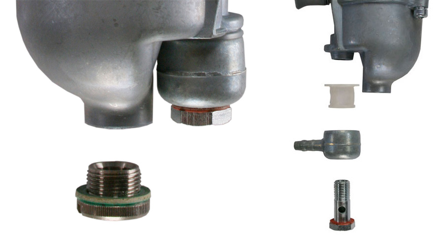
(d) Loosen the carburetter mounting nuts evenly. Take care not to jam or stress the flange on the studs by turning the nut on the tickler side of the body back too far in relation to the other nut.
(e) Remove the nuts and slide the carburetter off the mounting studs.
Dismantling
Mixing Chamber Top and Throttle Slide
(a) Thoroughly clean the outside of the carburetter
(b) Undo the two screws securing the mixing chamber top and withdraw the throttle valve and needle.
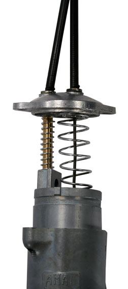
(c) Compress the throttle spring drawing it out of the slide. Holding the spring and top to one side to gain clearance, remove the needle and its securing clip.
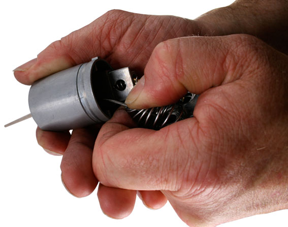
(d) Unhook the throttle cable from the slide once the needle is removed.
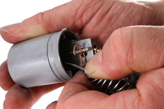
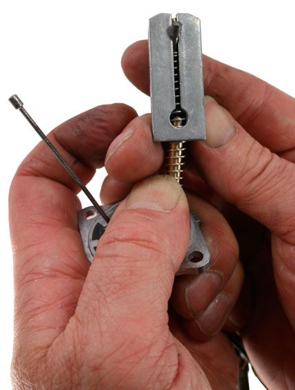
(e) Compress the air valve spring and unhook the cable to release the air slide, spring and brass tube.
Float Chamber
(a) Loosen the screws securing the float chamber ensuring that the float chamber will not drop once the screws are removed. If necessary tap the float chamber lightly with the handle of the screwdriver to break the gasket seal. Keep the float chamber level as you remove it to stop the float mechanism from falling out.
(b) Carefully separate the float chamber gasket from the body or float chamber.
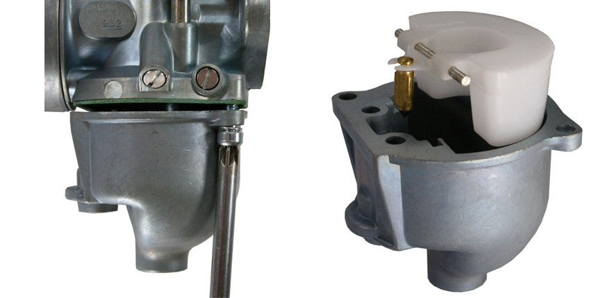
(c) Lift the float assembly from the float chamber and slide the float needle out of the float tabs.
(d) Slide the float spindle out of the float.
(e) Unscrew and remove the float chamber drain plug.
Mixing Chamber and Jets
Care should be taken when undoing brass jets. They are soft and easy to damage.
(a) A 5/16 BSF or 1/4 Whitworth spanner is required to undo and remove the jet holder from the bottom of the carburetter body.
(b) Use the Amal Jet Key (P/N 622/104) to undo and remove the Main Jet and Needle Jet from the Jet holder.
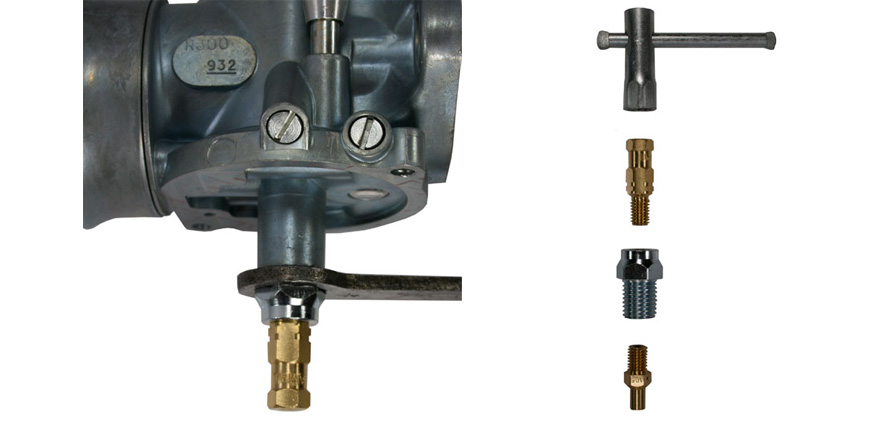
(c) Unscrew the Pilot Jet (if fitted) from the bottom of the Mixing Chamber.
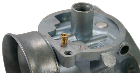
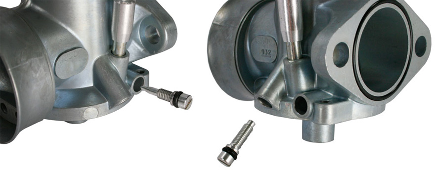
(d) Unscrew and remove the Pilot Air Screw. If you wish to replicate the setting on re-assembly, screw the screw fully home and make a note of the number of turns required, before removing it.
(e) Unscrew and remove the Throttle Stop Screw.
Cleaning And Inspection
Banjo and Filter
Clean and inspect banjos and filters. Plastic banjos should be replaced with metal banjos as they tend to harden and crack with age. Carefully inspect the filter and replace if torn or if there are deposits on the mesh that can't be removed. Rust fragments in the filter may indicate a problem in the petrol tank that can cause carburation problems in the future.

Float Chamber
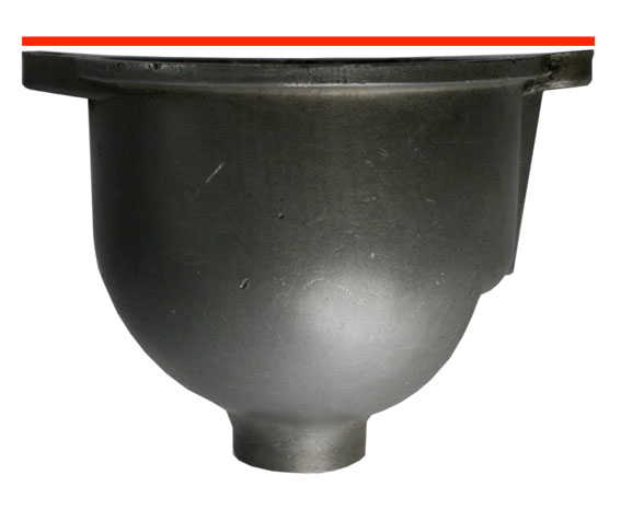
Inspect the gasket surface of the float chamber carefully for damage. The gasket surface should also be inspected for flatness. Light damage and irregularities can be remedied by dressing the surface using fine abrasive paper on a flat surface, or fine grinding paste on a plate of glass. However, if the surface is reduced too far, the depth of the slot for the float spindle will become too shallow and may cause difficulties with the operation of the float. Over-tightened Allen bolts, which are a popular modification, can bend the lugs and cause an air leak within the float chamber into the idle circuit. If the lugs are bent the float chamber should be replaced.
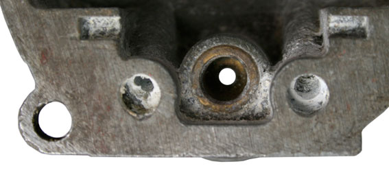
Ensure the two galleries in the casting are thoroughly clean.
Clean and inspect the float chamber drain plug ,this acts as a sump for the float chamber. If it shows signs of hardening with age, you should replace it. Early versions of the Mark 1 carburetter were not fitted with drain plugs. Those carburetters were fitted with a brass mesh sleeve filter around the Main Jet. It is recommended to replace this with a later type float chamber.
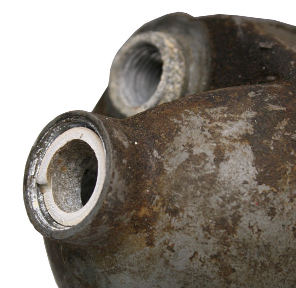
The float needle bears against the seat at the bottom of the brass seating bush. If the seat is damaged the float chamber will have to be replaced. Early models of the Concentric were fitted with plastic float needles. They should be replaced as a matter of course with the current Viton tipped float needles. Viton tipped needle valves are much more resistant to wear, but should be replaced if there are visible signs of wear, contamination, or damage.
If a punctured float is suspected, submerge the float completely in fuel for 15 minutes and shake it to see if any fuel has leaked into it. Check the float tabs for signs of distortion, and check that the float spindle is an easy rotating fit in the float, with no stiffness or excessive play.

The AMAL Concentric StayUp Float
The AMAL Carburetter Company, (Burlen Ltd) manufacturers of all genuine new AMAL Carburetters and spares Worldwide, have introduced a revolutionary new float for Mk1, Mk1.5 and Mk2 Concentric AMAL carburetters.
The adjustable height StayUp float is resistant to modern ethanol based fuels and has a military spec closed cell construction ,making it puncture proof. The ability to adjust the float arm allows for quick and easy minor alterations to float levels where required.
The material specified was used by the S.U Carburetter Company for military installations in the 1980s, where a guaranteed fail safe operation was critical. Due to the close link between S.U and AMAL today (both owned by Burlen Ltd), the secret behind the material has been released and upgraded for the manufacture of this float, making it virtually unsinkable.

Fuel Level
Although the Concentric carburetter will function across a wide range of fuel levels, an accurate fuel level is the foundation of the overall jetting of the carburetter and makes a significant contribution to the smoothness and performance of an engine
The fuel level is determined during manufacture by the position of the float needle valve seat and should not require adjustment under normal circumstances. For performance tuning or where a carburetter runs consistently rich or weak despite being fitted with the correct jetting, it may be desirable to check the fuel level to establish a calibrated basis for tuning, or re-establish the carburetter within the correct parameters.
Because there have been changes to the float chamber since the Concentric carburetter was introduced, and because there is no way of knowing what alterations may have been made by a previous owner, measuring the fuel level is the best way of setting up the float chamber.
The correct fuel level for all Mark 1 Concentric carburetters is 0.21" plus or minus 0.040" below the top edge of the float bowl. Thus when the needle valve is being held shut by the tangs of the float, the level of the fuel will be between 0.17" to 0.25" (4.33mm to 6.35mm) from the top of the bowl.
The fuel level can be checked by removing the float chamber and observing fuel running into it. The fuel flow should be sufficient to hold the needle valve open until closed by the action of the float. Insufficient fuel flow will cause the needle valve to seal under it's own weight before the float rises far enough to press the valve shut. The level of the fuel can then be measured down from the top surface of the float chamber.
The fuel level can also be checked by attaching a piece of clear tubing to the bottom of the float chamber. A plastic float chamber drain plug can be modified to mount a suitable spigot, such as an old jet, to attach the tubing. Route the tubing in a vertical position alongside the float chamber. Open the petrol tap and fill the float chamber with fuel. If the fuel level is in the correct range the fuel will rise in the tube to a point between 0.170" and 0.240" below the top edge of the float bowl. Start the engine and ensure the fuel level remains within the correct parameters.
The new Amal "Stay Up" float has stainless steel tangs which can be bent to alter the fuel level. The tangs can be easily adjusted by clamping the float in a vice up to the spindle hooks and tapping the body of the float gently in the direction required, until the required level is achieved.
Needle Valve
If your float chamber is fitted with a brass needle valve you may find the valve sealing under its own weight before the float has risen far enough to press it shut. Symptoms of this problem can be that the carburetter takes a long time to tickle, hesitates on pickup, and does not idle reliably. A Viton-tipped aluminium needle valve is now available that overcomes this problem. It is being fitted as standard equipment to all new Mark 1 Concentric carburetters.
Mixing chamber
Check and clean all threads in the mixing chamber. If no choke is fitted ensure the opening for the choke cable is sealed with a bolt, (P/N 4/137A) . Replace worn screws and ensure they are correctly fitted with spring washers.
Check the manifold flange against a flat surface to determine if it has been distorted by over-tightening or tightening to an uneven surface. If there is distortion (meaning, the throttle slide jams when the carburetter is bolted to the inlet manifold ) the carburetter needs to be replaced. Replace the O ring if there are any signs of hardening or damage.

The free length of the throttle spring should be 3". Replace if corroded, damaged or compressed. Inspect the air valve components for excessive wear or damage.
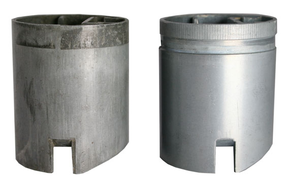
Inspect the throttle slide for excessive wear. If the wear pattern on the 'engine side' of the slide is visible (meaning a series of furrows or waves in the metal; or the step / groove at the top of the slide on the 'engine side' has been worn away) then the slide requires replacement. Eventually the mixing chamber body will also wear, to the point where the amount of air leaking around the throttle slide prevents accurate tuning of the carburetter. An replacement carburetter will be required. Wear to the carburetter will be much reduced by ensuring that an effective air filter is always fitted.
Check the tickler mechanism to ensure it moves smoothly. An upgrade kit is available to convert earlier ticklers to the later version with the large button.
Sleeving the Carburetter
There are solutions available to address 'body and slide wear' which involve boring the mixing chamber body and fitting a brass, steel or aluminium sleeve to either the body or the slide. Sleeving is not recommended for the following reasons;
(a) Thinning the walls of the mixing chamber makes the carburetter more prone to warping when the flange bolts are being tightened.
(b) Sleeving the carburetter to an incorrect clearance between slide and body will make the carburetter difficult ,or impossible to tune correctly.
(c) Inadequate wall strength and tight clearances can cause the slide to stick dangerously.
(d) Poorly executed sleeving can dislodge or damage the spray tube.
(e) Slides in bored mixing chambers can only be replaced with a further sleeved slide.
(f) Poorly sleeved carburetters can have the slide locating lug masked, to the point where the slide can override the locating slot and jam.
Pilot Circuit
Mark 1 Concentrics are equipped with two types of pilot jets. '2 Strokes' use a removable pilot jet which should be replaced if it is damaged or shows signs of oxidisation. '4 Strokes' generally use a pressed in bush pilot jet in the gallery behind the pilot air screw.
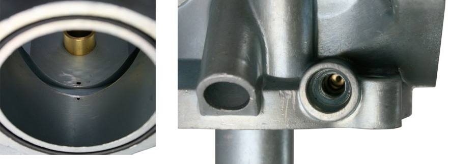
Fuel residues and oxidisation can cause problems with the pilot circuit, particularly in bikes that have been left standing with fuel in the carburetters for several months or more. It may be sufficient to clean the pilot circuit with an aerosol carburetter cleaner, stopping the various outlets selectively to ensure the entire system is clear. Do not forget to inspect the two pilot circuit outlet holes, either side of the slide location slot, in the bottom of the carburetter bore. If necessary the pilot bush can be cleaned by removing the pilot air screw.
By using a No 78 or 0.016"drill; hold securely in a suitable extension, rotate lightly in the bush to remove encrusted deposits.
Jets and Needles
Needle Jets are best replaced as a matter of course, especially if the age of the jet is unknown. They are the most vulnerable of the jets to wear with only .001" between sizes. A worn jet will cause very rich running between 1/4 and 3/4 throttle opening.
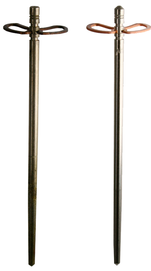
Replace the needle if there are signs of wear or corrosion, particularly on the parallel section. Check that the needle clip grips the needle securely and is not distorted in any way. The split in the clip is part of the design.
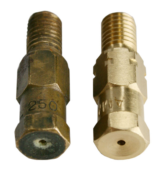
Main jets are resilient to wear but old jets, showing signs of oxidisation or any etched deposits, should be replaced as their ability to pass fuel may be affected.
In 1966 it was decided to standardise the 376/100 type jet for use in Monobloc, Concentric, GP and TT carburetters and changes were made to the jet to ensure compatability. The groove, machined across the hexagon of the jet on the right, indicates that it incorporates the modifications. New jets without the groove are not genuine, and are often extremely inaccurate.
Gaskets
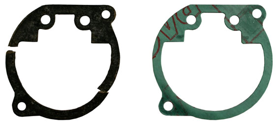
Always use new, genuine Amal gaskets and O rings to prevent leaks.
Checking the Specification
Manufacturer's original standard carburetter settings are available in the Amal Catalogue and on the Amal Website. However unless a bike has retained absolute originality, any changes to the engine, air filtration or exhaust arrangements (including modern replicas of original exhausts) may require adjustments to the carburetter.
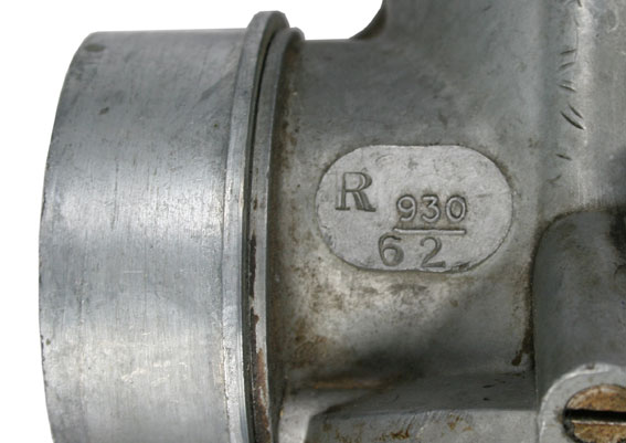
If you are not sure that you have a suitable carburetter, the numbers on the raised pad (on the side of the carburetter) can be used to identify it. 'R' or 'L' stamped on the pad indicates a left or right handed carburetter. A "B" originally indicated that the carburetter contained the upgraded needle and needle jet parts.
A three digit number beginning with a 6 or a 9 indicates the Series and bore size of the carburetter e.g. '624' indicates a 24mm 600 Series carburetter, '928' indicates a 28mm 900 Series carburetter.
The Specification Number stamped below the three digit number identifies the jetting and the original model of bike the carburetter was fitted to, e.g. '62' below 930, read as 930/62 identifies a 30mm 900 Series carburetter for a 1971-72 BSA B50SS.
It is also important to ensure that all the parts in your carburetter are correct for the engine type. The original Concentric carburetters used the same components for 4 Stroke and 2 Stroke. Carburetters are often found to contain a mismatch of components.
Interchangeable Parts
Spray Tubes

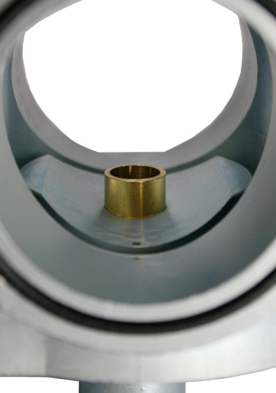
As a general rule the most noticeable difference between a 2 Stroke and 4 Stroke carburetter is the spray tube. The brass tube is visible as you look through the carburetter bore. 4 Stroke spray tubes are cut off straight, whereas 2 Stroke spray tubes are cut off at an angle, sloping towards the mounting flange. Some later '850cc Norton Commandos' use a spray tube with a square cutaway step. Triumph Triples use an angled spray tube cutaway from the mid point of the spray tube, rather than right across, as in the 2 stroke version. 2 Stroke and 4 Stroke bodies are not interchangeable and will not run correctly if used on the wrong type of engine.
Pilot Jets
When first introduced, all carburetters were fitted with a detachable pilot jet screwed into a threaded hole in the bottom of the carburetter body. This arrangement is retained for 2 strokes, but from 1968, was replaced for 4 strokes by a bush pressed into the gallery behind the pilot air screw.
The detachable pilot jet caused problems with some 4 Stroke engines. The remoteness of the jet from the two pilot circuit outlet holes, caused starting and idling problems on bikes with lower manifold vacuums. This could cause stalling during deceleration, due to a weak mixture. The introduction of the pilot bush moved the pilot jet nearer to the outlet holes, overcoming this problem. The bush has a flow rate, equivalent to 20cc/min. Carburetters fitted with a bush, retain the threads originally used to fit the removable pilot jet.
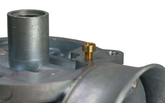
The removable two stroke pilot jet is stamped with a number from 15 to 200, indicating its flow rate in cc/min.
Needle Jets
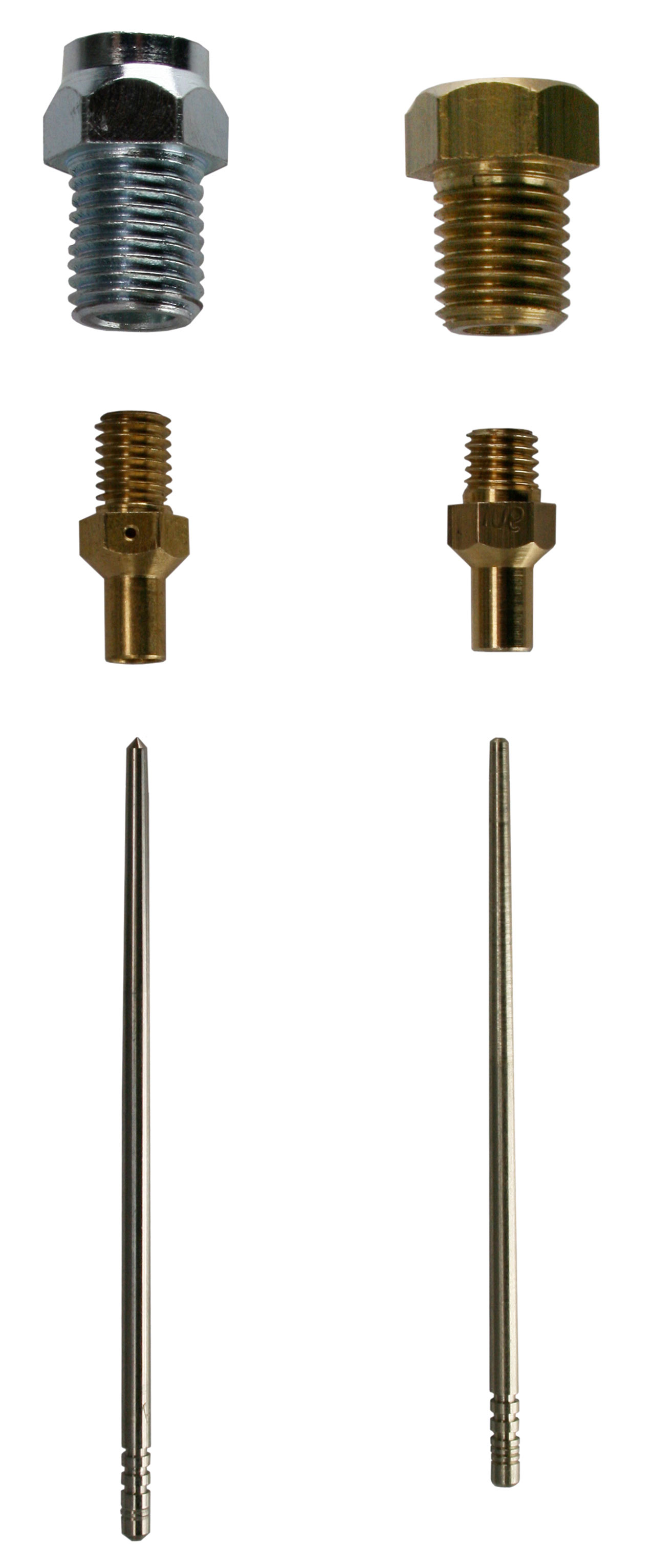
In 1969 a new needle jet, needle jet holder and needle , designed specifically for 4 stroke carburetters, was introduced to improve low to mid-range performance. The differences between the parts are;
| New | Old | |
| Needle | 2 21/32" (6.74cm) long - 2 identifying rings | 2 9/32" (5.79cm) long - 1 identifying ring |
| Needle Jet | 13/16" (2.06cm) long cross-drilled | 11/16" (1.74cm) long |
| Jet Holder | 7/8" (2.2cm) long | 3/4" (1.9cm) long |
Check to ensure that the parts in your carburetter are a matched set as above. A conversion kit (622/235) is available to update to the new parts.
2 Stroke and 4 Stroke needle jets are stamped to show their sizes in inches from 0.105 to 0.125. 4 Stroke needle jets have an air bleed hole drilled through the hexagon section. 2 Stroke jets have no cross-drilling.
Needle Markings. (600 and 900 Series Concentrics)
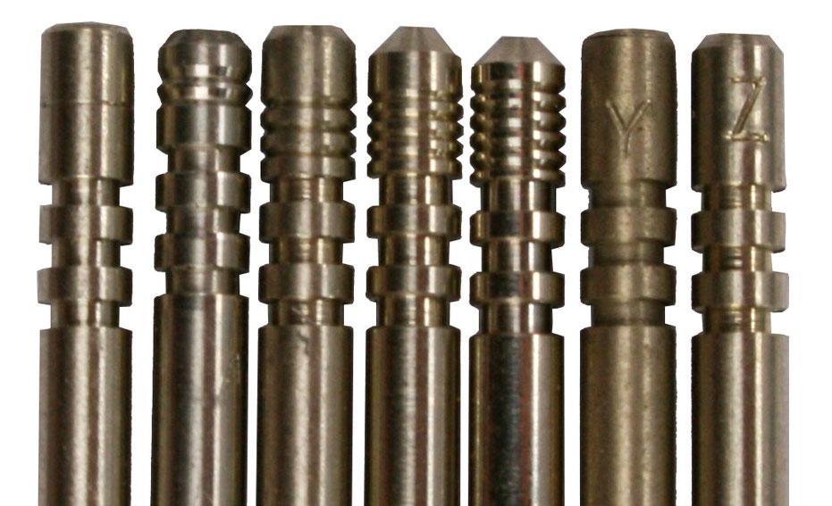
Needles have inscribed rings or letters stamped at the head of the needle above the clip grooves. All needles use a constant diameter down to the head of the tapered section. The taper helps to manage the transition from the Needle jet to the Main Jet and varies according to the type of engine or fuel.
| Markings | Where used | Part No: |
| 1 inscribed ring | 2 Stoke, 600 Series | 622/063 |
| 2 inscribed rings or 'U1' | 4 Stroke, 600/900 Series | 622/124 |
| 3 inscribed rings or 'X' | 2 Stroke, 900 Series | 928/063 |
| 4 inscribed rings | Norton 850, Triumph 250cc | 928/104 |
| 5 inscribed rings | Triumph T160 | 622/278 |
| Y | Alcohol, 600 Series | 622/099 |
| Z | Alcohol, 900 Series | 928/099 |
Throttle Slides
Throttles Slides are stamped with their identifying size on the bottom surface. Typical markings will be either 622 for a 600 Series slide, 928 for a 900 Series slide, an MB number which is a foundry mark, and a stamped number from 2 to 5 indicating the height of the cutaway on the inlet side of the slide.
The angled cutaway on the slide manages the transition from the pilot circuit, to the needle jet, when the bike is running. Smaller cutaways will richen the mixture, larger cutaways weaken it.

| 600 Series P/N | 900 Series P/N | Stamped as | Height of cutaway |
| 622/0602 | 928/0602 | 2 | 1/8" RICH |
| 622/06025 | 928/06025 | 2 1/2 | 5/32" |
| 622/0603 | 928/0603 | 3 | 3/16" |
| 622/06035 | 928/06035 | 3 1/2 | 7/32" |
| 622/0604 | 928/0604 | 4 | 1/4" |
| 622/06045 | 928/06045 | 4 1/2 | 9/32" |
| 622/0605 | 928/0605 | 5 | 5/16" LEAN |
Main Jets are calibrated and numbered according to the rate of flow in cc/min which is stamped on the side to identify them. Jets cannot be reamed but must be replaced if a larger size is required
Genuine Spares
Many Amal parts are easy to copy but difficult to replicate. The simplicity of tuning and proper operation of the carburetter reflects the subtleties of the design. There are many crude and poor quality copies of Amal parts available, made from incorrect, rapid wearing materials, which will cause difficulties in the tuning and operation of the carburetter. All genuine Amal parts are now individually packaged and sealed for easier identification and carry a 12 month warranty from the date of purchase.
Re-assembling the Carburetter
Mixing Chamber
(a) Fit a new O ring to the throttle stop screw and install the screw.
(b) Fit a new O ring to the Pilot Air Screw. Wind the screw fully home then back it out between 1 ¼ and 1 ½ turns for an initial setting.
(c) Using the Amal Jet Key, install the Needle Jet in the top of the Needle Jet holder and tighten it securely. Take care not to over-tighten brass jets as they can break.
(d) Using the Amal Jet Key install the Main Jet into the bottom of the Needle Jet Holder and tighten it securely.
(e) Install the jet assembly into the bottom of the Mixing Chamber and tighten to a torque of 10lb/ft.
(f) For Two Strokes, carefully install the Pilot Jet into the bottom of the Mixing Chamber.
Float Chamber
(a) Fit the spindle and Needle Valve to the Float and lower the assembly into the float chamber.
(b) Fit a new gasket to the float chamber, slide the securing screws through the holes and gasket to align the gasket and check that no part of the gasket interrupts the movement of the float.
(c) Lower the Mixing Chamber onto the Float Chamber, ensuring the float chamber is the correct way round and the pilot jet (if fitted) is aligned with the recess in the Float Chamber. Ensure the float assembly does not become dislodged.
(d) Tighten the Float Chamber screws securely.
(e) Install the Float Chamber Drain Plug with a new fibre washer.
Throttle Slide and Top
(a) Insert the choke cable into the Mixing Chamber Top and assemble onto it the brass choke tube, the spring and the alloy air slide. Compress the spring and hook the cable nipple into its recess in the end of the air slide. Fit the Air Slide into the Throttle Slide.
(b) Insert the throttle cable into the Mixing Chamber Top and slide the Throttle Spring over it. Compressing the Throttle Spring, hook the cable nipple into its recess in the Throttle Slide.
(c) Assemble the Needle with the Needle Clip in the required groove.
(d) Compress the Throttle Spring, drawing it out of the Throttle Slide and to one side. Drop the needle into the slide, engaging the end with the central hole and drawing it down so that the needle clip sits in the circular recess. Lower the spring carefully so that it does not disturb the needle.
(e) Fit the Throttle Slide into the Mixing Chamber body. Watch to ensure that the end of the needle enters the needle jet and does not become snagged on the side, dislodging the needle clip. Engage the lug on the slide with the slot in the body and lower it home.
(f) Ensure the lid is fitted correctly with the pip on the side of the lid, pointing to the rear of the carburetter and securely tighten the screws.
(g) Adjust the Throttle Stop Screw so that it just begins to engage against the slide when the slide is closed.
(h) Fit a new O ring into the recess in the manifold flange.
(i) Open and close the throttle to ensure that the slide moves smoothly in the body and returns sharply when the throttle is released.
Replacing the carburetter
Always replace the carburetter fully assembled with the float chamber and mixing chamber top attached. The manifold flange and any heat reducing spacers should be carefully checked and dressed if necessary to ensure they are flat. Bolting the carburetter to a distorted flange or uneven spacer, increases the risk of carburetter body or flange distortion.
Mark 1 carburetters are not designed to bolt tightly to the intake flange and may distort if overtightened. It is only necessary to compress the O ring seal to ensure air tightness. When correctly tightened the carburetter flange and engine manifold should be just touching. Nyloc nuts should always be used to mount Amal Mark 1 carburetters and should be tightened to no more than 4 ft lb.
Ensure that throttle and choke cables are able to open and shut freely when the petrol tank is replaced on the bike, and are not affected by moving the handlebars from side to side.
Troubleshooting
The carburetter is one of the more reliable but most accessible systems on a motorcycle. When considering a suspected carburetter fault ,bear in mind that air leaks or obstructions in the induction or exhaust systems, incorrect valve clearances, incorrect ignition timing, worn valve guides or piston rings can all affect the performance of the carburetter, while ignition faults such as worn advance/retard units can produce symptoms that resemble a carburetter fault.
